PERFECT
EXPERIENCED
& HIGH QUALITY SERVICE


LEVEL GAUGES
TANK FILLER
BREATHERS
RETURN LINE
SUCTION STRAINERS
GIANT & DESICCANT
AIR BREATHERS
General Information
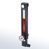
STAUFF Level Gauges SNA
Visual fluid level indication in hydraulic re-
servoirs with maximum tank pressures not
exceeding 2 bar / 29 PSI
Nominal Sizes and Designs
▪ 6 nominal sizes from 76 mm / 2.99 in to
305 mm / 12.00 in
▪ Display either undivided (SNA 076 ... 176)
or subdivided by strut(s) into 2 (SNA 254)
or 3 sections (SNA 305)
Media Compatibility
▪ Suitable for use with Mineral and Petroleum
based hydraulic fluids (HL and HLP)
Materials
▪ Housing made of Steel St 12, black powder coating
▪ Sight tube and plugs made of Polyamide (PA)
▪ Sealings made of NBR (Buna-N®)
▪ Scale plate made of PVC
Special sight tube materials for improved UV or chemical
resistance and use with special media (such as
bio-degradable fluids, diesel oils, gasolines, etc.) as well
as special sealing materials, e.g. FPM (Viton®), and scale
plate materials, e.g. Aluminium, are available on request.
Technical Data
▪ IP 65 protection rating: Dust tight and protected
against water jets (IP 67 on request)
▪ Operating temperature range:
-30 °C ... +80 °C / -22 °F ... +176 °F
Options / Accessories
▪ Neutral or custom-designed scale plates
▪ Red / blue capillary tube thermometers with a dual
Celsius / Fahrenheit scale and a temperature display
range of up to +80 °C / +180 °F
▪ Dial thermometers with probe and a Celsius or a
dual Celsius / Fahrenheit scale with a temperature
display range of up to +100 °C / +200 °F
▪ Thermo switches
▪ Temperature sensors
STAUFF Level Gauges SNK
Visual / electrical fluid level indication in
hydraulic reservoirs with maximum tank
pressures not exceeding 2 bar / 29 PSI
Nominal Sizes and Designs
▪ 5 nominal sizes from 127 mm / 5.00 in to
305 mm / 12.00 in
▪ Display either undivided (SNK 127 ... 176)
or subdivided by strut(s) into 2 (SNK 254)
or 3 sections (SNK 305)
Media Compatibility
▪ Suitable for use with Mineral and Petroleum
based hydraulic fluids (HL and HLP)
Materials
▪ Housing made of Aluminium, black powder coating
▪ Sight tube and plugs made of Polyamide (PA)
▪ Float made of Polyamide (PA)
▪ Sealings made of FPM (Viton®)
Special sight tube materials for improved UV or chemical
resistance and use with special media (such as
bio-degradable fluids, diesel oils, gasolines, etc.) as well
as special sealing materials are available on request.
Electrical Specifications
▪ Magnetic float activates switch when fluid level drops below
contact level within 60 mm / 2.36 in of lower banjo bolt
▪ Available as a break contact (normally closed)
or make contact (normally open)
Technical Data
▪ IP 65 protection rating: Dust tight and protected
against water jets (IP 67 on request)
▪ Operating temperature range:
-30 °C ... +80 °C / -22 °F ... +176 °F
General Information
Features
▪ Suitable for Mineral Oil and HFC fluids,
other fluids on request
▪ Either 1 or 2 level contacts available
▪ 1 integrated temperature sensor (optional)
▪ Standard electrical function:
Level contacts: Normally closed, opens with
falling level
Temperature contacts: Normally closed, opens
with rising temperature
STAUFF Level-Temperature Switches SLTS are available
with other electrical functions on request.
Options
▪ 1 NPT and others availble on request
▪ max. 115 Volt switching (for thread N16 only)
Technical Data
Materials
▪ Stem: Brass
▪ Float/Sealing: NBR (Buna-N®)
▪ Max. operating temp.: +80 °C / +176 °F
Electrical Data and Output
▪ Max. current level contact: 0.5 A
▪ Max. current temp. contact: 2.0 A
▪ Contact load level contact: 10 VA
▪ Max. operating voltage: (See ordering code)
▪ Specific gravity of fluid: ≥0,8 kg/dm3
▪ Hysteresis: +18 °C / +64.4 °F
Protection Rating
▪ IP 65 protection rating: Dust tight and protected
against water jets
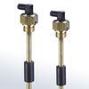
Level-Temperature Switch SLTS
The STAUFF Level-Temperature Switches (SLTS Series) are unique in their design and modularity.
One of the greatest advantages is the ability of the end-user to adjust the switching level.
The internal support wire carrying the level and temperature switches makes it a simple and
quick job to change the level switch position.
General Information
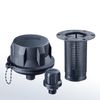
STAUFF Metal Filler Breathers
SMBT/SMBB/SMBP
Designed to be used as filler ports for
hydraulic reservoirs, allowing the reser-
voir to breathe whilst protecting it from
contamination found in harsh environ-
ments
Types
▪ SMBT-47 (Screw-in version; Cap Ø 47 mm / 1.85 in)
▪ SMBB-47 (Bayonet version; Cap Ø 47 mm / 1.85 in)
▪ SMBT-80 (Screw-in version; Cap Ø 80 mm / 3.15 in)
▪ SMBB-80 (Bayonet version; Cap Ø 80 mm / 3.15 in)
▪ SMBP-80 (Push-on version; Cap Ø 80 mm / 3.15 in)
Materials
▪ Breather cap made of Steel, zinc/nickel-plated
(Fe/Zn Ni 6) and free of hexavalent chromium
CrVI (standard option); chrome-plated and
epoxy-coated versions available
▪ Bayonet flange made of Steel, zinc-plated
▪ Basket made of Steel, zinc-plated or Polyamide (PA)
▪ Dipstick adaptor made of Polyamide (PA)
▪ Sealings made of Cork (for filler breathers without
pressurisation) or NBR (Buna-N®) (for pressurised filler
breathers)
Options / Accessories
▪ Metal basket
▪ Plastic basket
▪ Pressurisation up to 0,7 bar / 10 PSI
▪ Air filter element
▪ Locking feature
▪ Dipstick adaptor
▪ Plastic dipstick with integrated anti-splash feature
▪ Extended bayonet flange
▪ Weld riser
▪ Side mount bracket (Polyamide)
▪ Side mount bracket (Aluminium)
Some options / accessories may only be
available for particular sizes or designs!
STAUFF Plastic Filler Breathers SPB
Designed to be used as filler ports for
hydraulic reservoirs, allowing the reservoir
to breathe whilst protecting it from conta-
mination found in harsh environments
Types
▪ SPB 1 (Screw-in version; Cap Ø 45 mm / 1.77 in)
▪ SPB 2 (Screw-in version; Cap Ø 70 mm / 2.76 in)
▪ SPB 3 (Screw-in version; Cap Ø 101 mm / 3.98 in)
▪ SPB 4 (Bayonet version for clamping jaw installation
to a single mounting hole; Cap Ø 101 mm / 3.98 in)
▪ SPB 4 (Bayonet Version with six-hole bolt pattern for flange
interfaces similar to DIN 24557-2; Cap Ø 101 mm / Ø3.98 in)
Materials
▪ Made of non-corrosive materials
▪ Body and cap made of glass-fibre reinforced Polyamide (PA)
▪ Sealings made of NBR (Buna-N®)
Consult STAUFF for alternative materials.
Technical Data
▪ Operating temperature range:
-40 °C ... +120 °C / -40 °F ... +248 °F
Options / Accessories
▪ Plastic basket (800 μm)
▪ Telescopic plastic basket (800 μm)
▪ Pressurisation up to 0,7 bar / 10 PSI
▪ Air filter element
▪ Anti-splash feature
▪ Plastic dipstick with integrated anti-splash feature
▪ Weld riser
▪ Side mount bracket (Polyamide)
▪ Side mount bracket (Aluminium)
Some options / accessories may only be
available for particular sizes or designs!
General Information
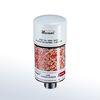
STAUFF Desiccant Air Breathers SDB
Combination of air breather and water removal filter
Features
▪ Available in 4 different sizes
▪ Diameter of Ø100 mm / Ø3.94 in or Ø130 mm / Ø5.12 in
▪ Refillable with drying agent (non-toxic ZR gel grain)
or a mix of drying agent and active carbon
▪ Drying agent capable in changing colour from
Red to orange with increasing moisture
▪ Without dangerous substances according to
EC Council directives 99/45/EC and 2001/60/EC
▪ Replaceable air filter element SGB
▪ Connection: Male BSP thread (ISO 228)
on Stainless Steel tube
▪ Available with adaptor plate to simplify installation and
to enable the use of a visual contamination indicator
Options / Accessories
▪ Adaptor plate
▪ Visual contamination indicator
▪ Drying agent refilling material
▪ Active carbon refilling material
▪ Replacement air filter element
STAUFF Giant Air Breathers SGB
Originally designed to be used as replaceable air
filter elements for STAUFF Desiccant Breathers, they
can also be used as seperate air filters for hydraulic reservoirs
Features
▪ Diameter of Ø68 mm / Ø2.68 in (SGB-060),
▪ Ø100 mm / Ø3.94 in (SGB-090) or
▪ Ø130 mm / Ø5.12 in (SGB-120)
▪ Equipped with female BSP thread (ISO 228)
▪ Including sealing made of NBR (Buna-N®)
Options / Accessories
▪ Threaded breather adaptors
(for direct installation on top
of hydraulic reservoirs)
General Information
STAUFF Suction Strainers SUS
Designed as in-tank suction strainer elements for direct installation into suction lines of pumps; should always be installed below the minimum fluid level of the reservoir
Features
▪ Available with female BSP thread (ISO 228)
or female NPT thread (ANSI B1.20.1)
Materials
▪ Threaded end cap made of glass-fibre reinforced
Polyamide (PA) or Aluminium
▪ Lower end cap and support tube made of Steel, zinc-plated
▪ Standard filter material is Stainless Steel Mesh (125 μm);
alternative micron ratings of 60 μm and 250 μm on request
Consult STAUFF for alternative materials.
Media Compatibility
▪ Suitable for use with Mineral and Petroleum based
hydraulic fluids (HL and HLP)
Technical Data
▪ Operating temperature range:
-20 °C ... +100 °C / -4 °F ... +212 °F
Options
▪ Integrated bypass valve with an opening pressure
of 0,2 bar (3 PSI) to reduce the risks of high-pressure
drops that can be caused by contaminated strainer
elements or high-viscosity fluids
Special sizes, designs, materials and configurations
are available on request. Consult STAUFF for details.
General Information
STAUFF Diffusers SRV
Designed for direct installation into
return lines to reduce fluid aeration,
foaming and noise; should always be
installed below the minimum fluid level
Features
▪ Available with female BSP thread
(ISO 228) or female NPT thread
(ANSI B1.20.1)
Design and Materials
▪ 2 concentric tubes with inner spaced holes
▪ Installation below the minimum fluid level of the
reservoir with the plain area facing the pump inlet
▪ Threaded end cap made of Aluminium
▪ Other components made of Steel, zinc-plated
Special sizes, designs, materials and configurations
are available on request. Consult STAUFF for details.
Media Compatibility
▪ Suitable for use with Mineral and Petroleum based
hydraulic fluids (HL and HLP)
Technical Data
▪ Operating temperature range:
-20 °C ... +100 °C / -4 °F ... +212 °F
▪ Max. working pressure: 20 bar / 290 PSI
STAUFF Return Line Bushings SRF
Designed as tubular support, vibration
and noise absorber and protection
element for rigid return lines entering
the hydraulic reservoir
Features
▪ For all commonly available Metric and
imperial pipe and tube diameters from
6 ... 42 mm and 1/4 ... 1-1/2 in
▪ Easy installation
▪ Chemically resistant against oil and solvents
Materials
▪ Bushing made of Polypropylene (PP) or
Thermoplastic Elastomer (TPE) with a
hardness degree of 87 Shore-A
Media Compatibility
▪ Suitable for use with Mineral and Petroleum based
hydraulic fluids (HL and HLP)
General Information
Bell Housings
Bell housings are the mechanical elements used to connect an electric motor equipped with standard flange to a hydraulic pump, thus forming the pump/motor unit. The bell housings of this range allow to establish a perfect assembly between electrical motors with standard flange up to 270 kW and the majority of the hydraulic pumps available on the world market.
They are produced in aluminium alloy and are divided into two categories:
▪ Single piece bell housings
▪ Composite Bell housings
▪ Base Bell housing + flange
▪ Base Bell housing + distance ring + flange
Materials and Material Properties:
▪ Bell housings: Aluminium alloy for die-and shell-casting
▪ Centering rings: Cut and zinc-plated sheet metal
▪ Working temperature: -30°C to +80°C
On request, all our bell housings can be supplied with specific coating or surface treatment to make them also fully suitable under rough circumstances.
General Information
Curvic Gear Couplings
Curvic Gear Couplings comprise two crowned and barreled steel hubs, coupled by a matching polyamide sleeve. Hubs are fully machined and zinc plated for corrosion protection.
Curvic Gear Couplings are available in three standard sizes for the majority of applications.
Series 28
For use on shafts from 9mm to 28mm diameter. Rated to a maximum speed of 5000rpm and 1.00hp (.75kw) per 100rpm.
Series 42
For use on shafts from 13mm to 42mm diameter. Rated to a maximum speed of 5000rpm and 1.75hp (1.32kw) per 100rpm.
Series 55
For use on shafts from 17mm to 55mm diameter. Rated to a maximum speed of 4000rpm and 8.00hp (6kw) per 100rpm.
Features:
▪ Compact design
▪ Low inertia
▪ Quiet running
▪ Alignment compensation (see chart)
▪ Zero maintenance
▪ Chemical and corrosion resistant
▪ Absorption of vibration
▪ Easy assembly
▪ Wide temperature range
General Information
The STAUFF Clean System comprises of a pneumatic launcher and a range of specially designed nozzles and projectiles. The launcher uses standard industrial compressed air pressure between 6 and 8 bar / 87 and 116 PSI to propel a foam projectile through the nozzle and into the pipe, tube or hose bore to have their inside surface cleanedfrom any unwanted contamination. This provides a safe and environmentally friendly tool that requires little formal expertise to operate and apply.
The launcher is the part of the system that controls the air supply to propel the projectile from start to finish of the cleaning job.
The nozzles are specially designed to affect an airtight seal on any pipe, tube or hose with or without end fittings. Its main purpose is to compress the foam projectile allowing it to enter the internal diameter of the pipe, tube or hose to be cleaned.
The projectile is the part of the system that does the cleaning: The foam projectile is sized to be approximately 15 % larger than the internal diameter of the pipe, tube or hose to be cleaned. The compression of the projectile against the internal wall cleans the internal surface and expels any loose contaminants from the end of the pipe, tube or hose.
The STAUFF Clean System is available as separate components or in a variety of kit forms comprising various nozzle types, adaptor and launcher, all contained in a heavy duty carrying case.
TEMPERATURE SWITCHES
BELL HOUSING
PIPE, TUBE & HOSE CLEANING SYSTEM
COUPLING